Electrical Designs
Let ICD handle all of your Electrical Design needs. We offer almost everything for your project, from a simple schematic, interconnections, block and line drawings, point to point, and more. New or updated designs or reverse engineered documentation of your existing equipment.
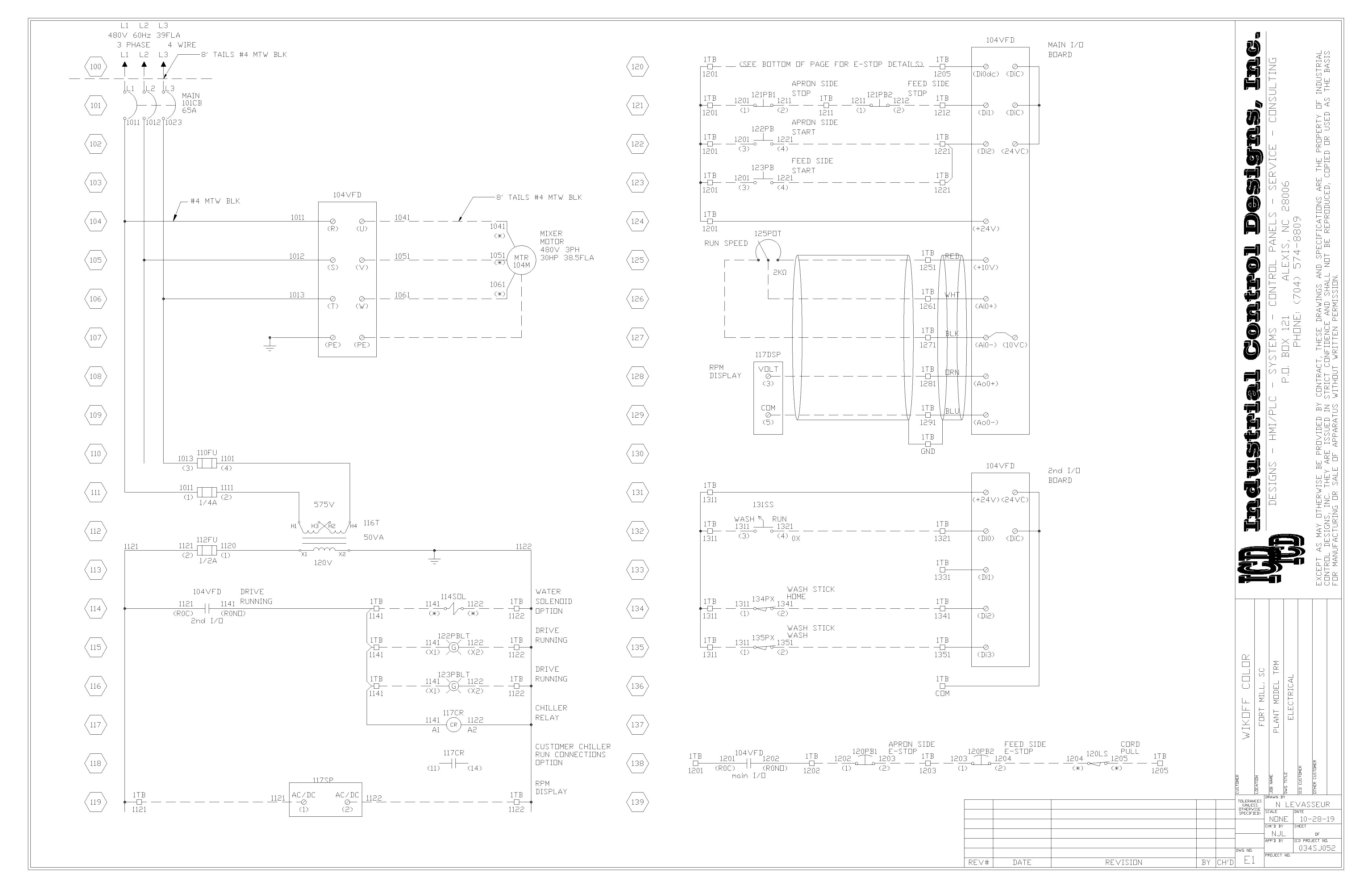
Controls and Schematics
ICD uses schematic ladder drawings for the design of control cabinets and equipment. With these drawings, panel shops or end users are able to wire the electrical controls equipment with the proper components, wire sizes, labels, and techniques for an exceptional job. Device, panel, and cable/conduit identification is also a must.
Let the professionals at ICD design your next control equipment project.
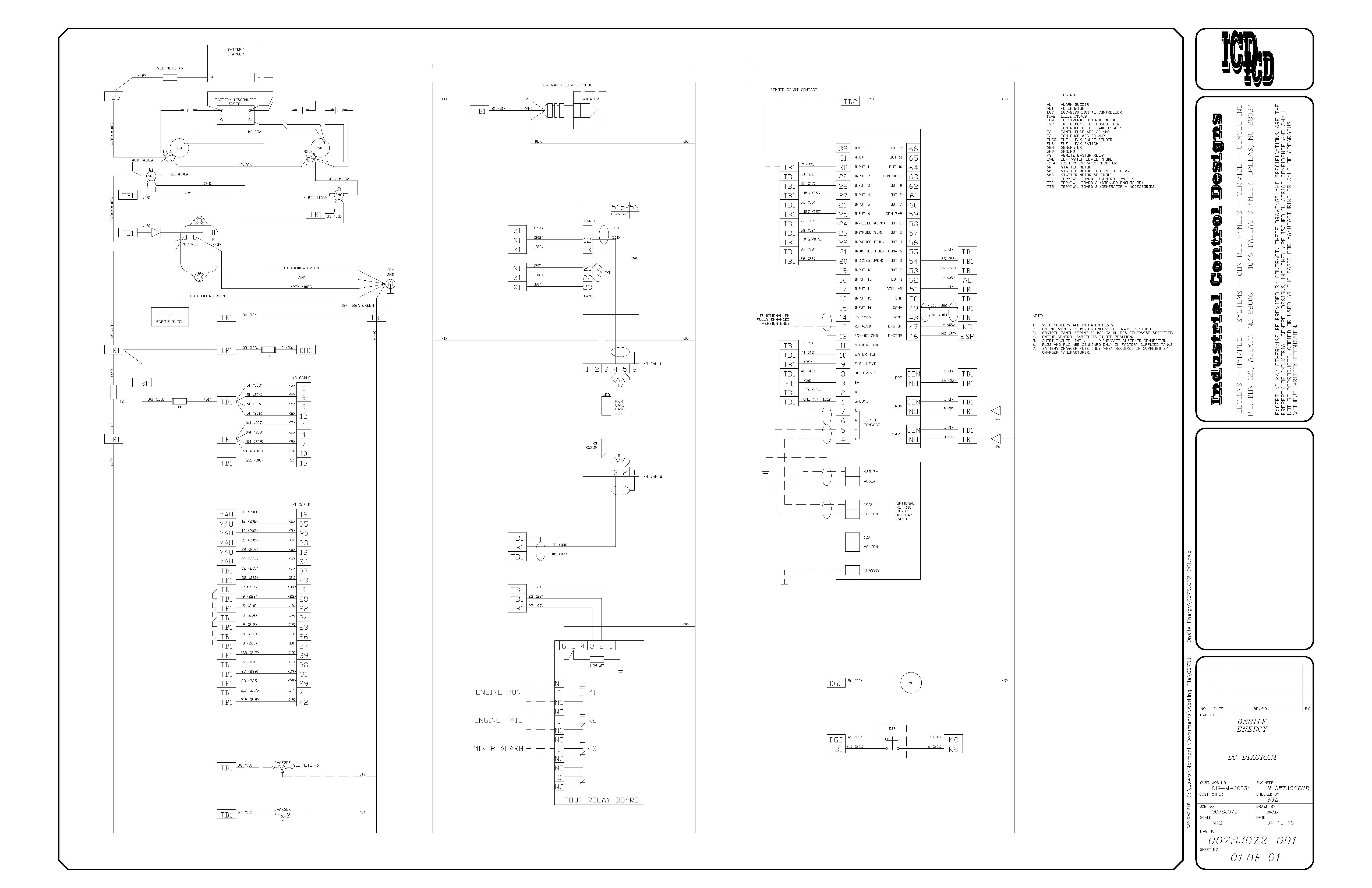
Wiring Diagrams
Wiring diagrams, a simplified conventional pictorial representation of electrical circuits, are sometimes needed. These will show devices and components in real life with wire connections made from point to point.
A wiring diagram usually gives information about the relative position and arrangement of devices and terminals on the devices to help build or service the device.
ICD uses wiring diagrams to help customers quickly define components and how they are hooked up with their systems. This allows for quicker troubleshooting solutions and less downtime in the production environment.
Power and Distribution
Let ICD provide you with highly detailed one-line diagrams and/or conduit risers of your plant distribution or larger control systems.
One-line diagrams are used in large equipment and plant power distribution to show power flow. Electrical elements such as disconnect switches, fusing, circuit breakers, transformers, capacitors, motors/loads, bus bars, conductors, conduits, cables, and sizes are shown by standardized schematic symbols. Instead of representing each of the three phases with a separate line or terminal, only one conductor is represented. It is a form of block diagram graphically depicting the paths for power flow between entities of the system. Elements on the diagram do not represent the physical size or location of the electrical equipment. Still, it is a common convention to organize the diagram with the same left-to-right, top-to-bottom sequence as the switchgear or other apparatus represented.
A one-line diagram can also be used to show a high-level view of conduit runs for a PLC control system or conduit riser diagrams.

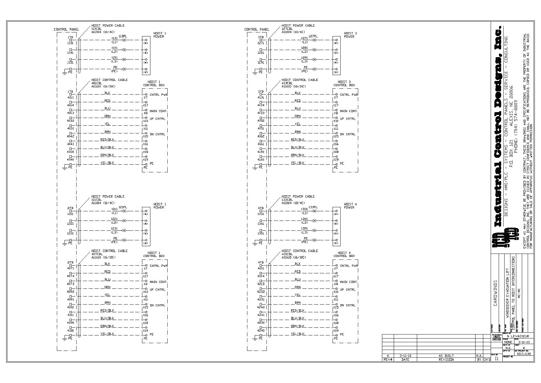
Interconnection Diagrams
ICD can provide detailed interconnection block diagrams or drawings showing the interconnection between each device, including instrument, junction box, panel, etc. This drawing can provide a glance view of an overall connection of a system. Our interconnection block diagrams provide details of every cable or conduit run from the field instrument up to the control system. An interconnection block diagram will also indicate cable and conduit numbers and is usually accompanied by a conduit/cable list.
With an interconnection drawing from ICD, customers or contractors can easily hook up and verify connections between the panels, sub-assemblies, and devices.
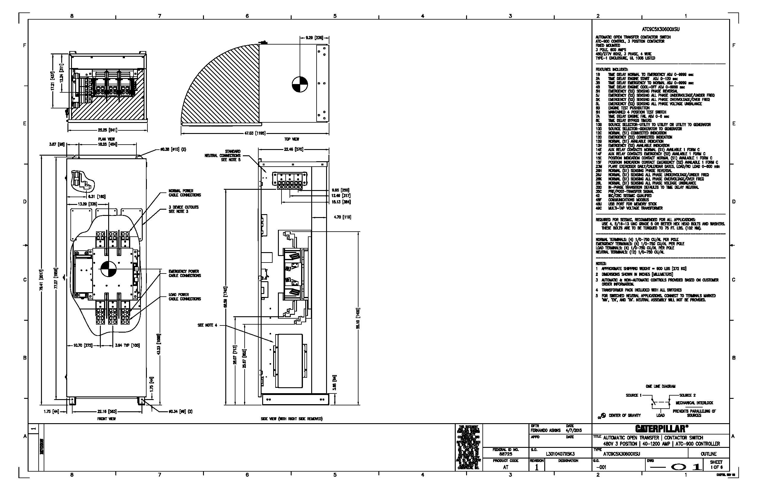
Layouts
At ICD, our control panel layouts are thoroughly detailed, making it easy to be built by us or sent to any fabrication company to build your project to specifications without detailed questions slowing down the process.
ICD provides highly detailed pictorial layouts, dimensional data, drill/cutout drawings, and all notations to convey the design.
We also offer plant floor layouts to provide installers with panel/equipment locations and conduit/cable runs. This reduces the risk of missing wiring.
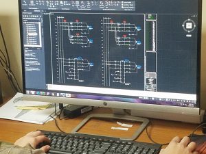
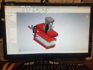
AutoCAD Services
At ICD, our engineers are well versed in all the different applications of AutoCAD. Whether you need a wiring diagram or a 3D model of your new machine, all of your needs can be met in one place.
ICD uses many different versions of AutoCAD, including:
- Electrical
- Mechanical
- Inventor
- Architectural
- Navis Works
- 3DS Max
- Raster Design
- MEP
- P&ID
- Plant 3D